A Complete Liquid Filling Line Must be Engineered as a Single System – Part 2
A Complete Liquid Filling Line Must be Engineered as a Single System –
Part 2
Successful projects do not end at startup: robust commissioning, operator training, and structured preventative maintenance are essential to sustain performance, especially in harsh caustic environments where equipment is expected to last for decades.
1. Line design fundamentals
Designing a complete liquid filling line starts by defining products, packages, speeds, and environment, then selecting and integrating machines to meet those requirements.
Key upfront considerations include:
● Product: viscosity, foaming, corrosivity, temperature, flammability, and required fill accuracy.
● Package: bottle material and geometry, caps and closures, labels, cases, and pallet pattern.
● Performance: target bottles per minute, changeover frequency, and required uptime/OEE.
● Environment and compliance: caustic or hazardous area classification, sanitation, and applicable codes.
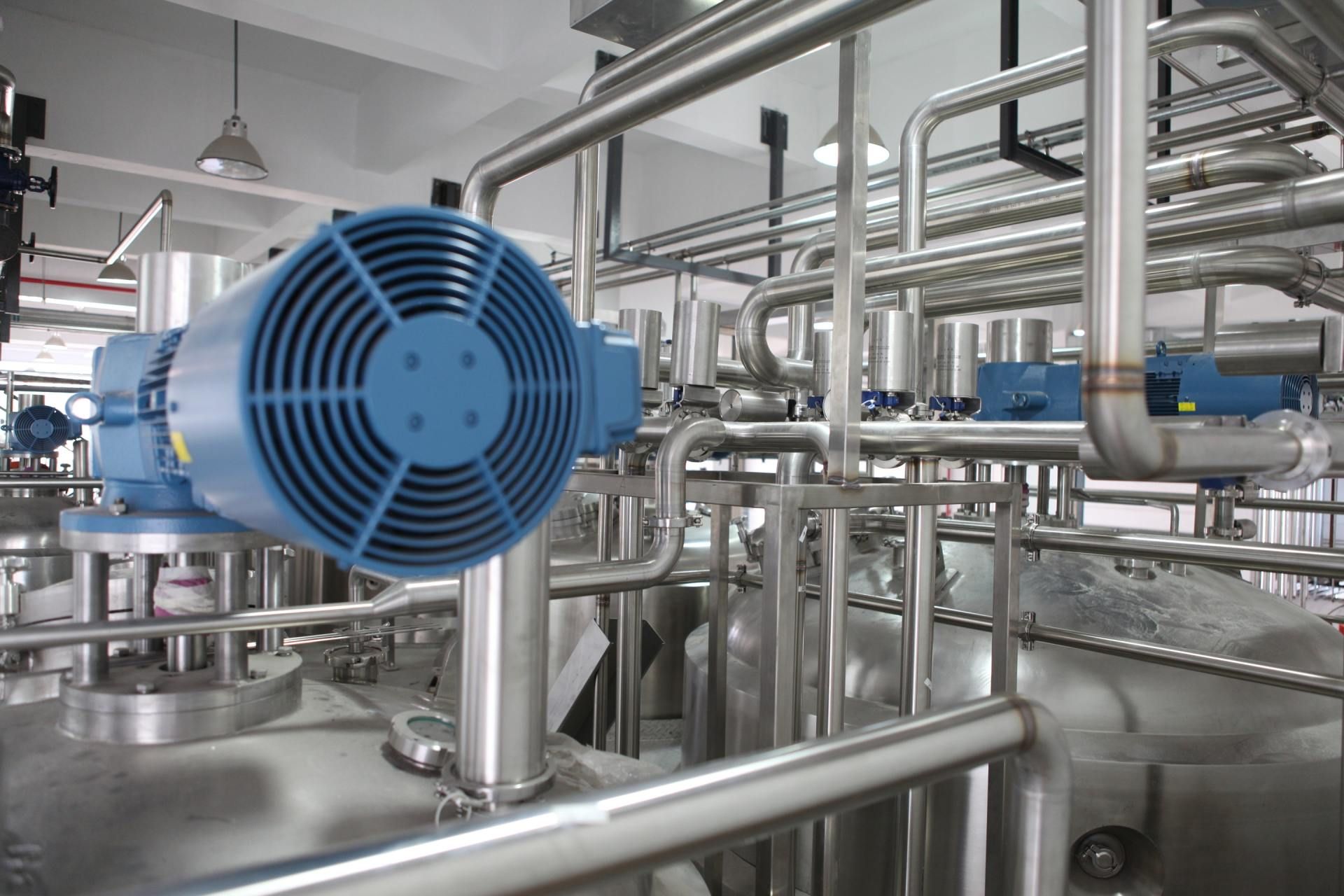
For caustic or corrosive chemicals, line design must incorporate compatible materials (e.g., high‑grade stainless steel, engineered plastics), robust seals, and enhanced safety systems to protect operators and extend machine life.
2. Bottle unscrambler
An automatic bottle unscrambler receives bulk, empty bottles and delivers them single file, oriented correctly, to the main conveyor.
Function
● Accepts randomly oriented bottles from a hopper or elevator.
● Uses mechanical or centrifugal devices and guides to orient bottles neck‑up.
●
Discharges a controlled stream of bottles to the infeed conveyor feeding the rinser/cleaner.
Design considerations
● Bottle range: height, diameter, shape (round, square, oval, flat), and material.
● Changeover: tool‑less or quick‑change parts for different bottles.
● Integration: speed‑matching with downstream conveyor and accumulation to avoid starve/block conditions.
In a high‑corrosivity environment, the unscrambler’s contact parts and frame should use corrosion‑resistant materials and allow easy washdown.
3. Bottle cleaning/rinsing machine
The bottle cleaner or rinser removes dust, particulates, and potential contaminants from the interior (and sometimes exterior) of bottles before filling.
Function
● Receives bottles from the unscrambler via conveyor.
● Inverts bottles or uses nozzles to blow air, vacuum, or rinse medium (e.g., filtered air, water, or product) through containers.
●
Discharges cleaned bottles in the correct orientation to the filler infeed.
Design considerations
● Cleaning method: air/vacuum for dry operations vs. liquid rinsing for higher hygiene or dusty environments.
● Containment: capture and filtration of blown‑off particulates or spent rinse liquids.
●
Chemical compatibility: all wetted components and seals must withstand the product or rinsing medium, especially with caustic lines that may use alkaline cleaning solutions.
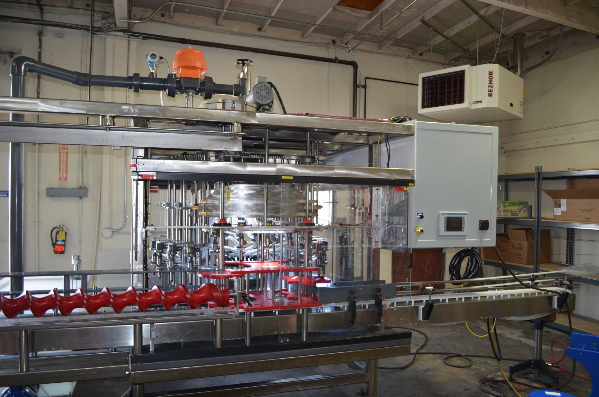
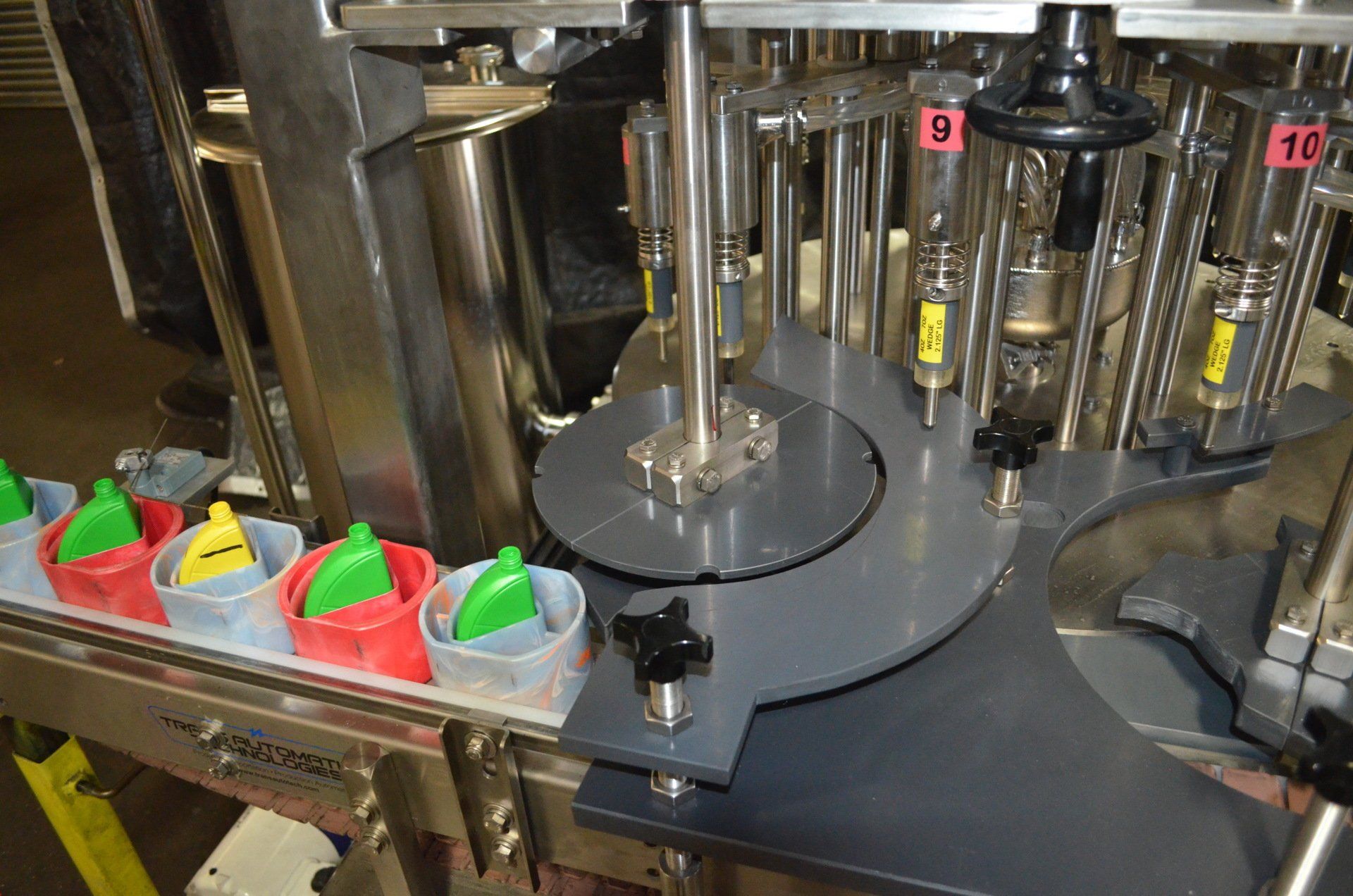
4. Liquid monobloc filler‑capper
A monobloc filler‑capper combines precision filling and capping on a single frame, with bottles controlled by synchronized starwheels or indexing systems for accurate, high‑speed operation.
Function
● Infeeds bottles from the cleaner via timing screws and starwheels or indexing tables.
● Fills bottles to a set volume, weight, or level using technologies such as piston or flow‑meter systems, often with servo control for accuracy.
● Transfers filled bottles directly into a capping turret or station that applies, torques, and verifies caps.
●
Discharges finished, capped bottles to the labeler conveyor.
Design considerations
● Fill technology: select piston vs. flow‑meter or other volumetric systems based on viscosity, foaming, solids, and accuracy requirements.
● Speed and configuration: rotary vs. inline, number of filling heads, and capping heads sized for target BPM.
● Caustic/ hazardous duty: corrosion‑resistant wetted parts, sealed electrical enclosures, intrinsically safe components, and appropriate area‑classification design.
● Controls: integrated PLC, motion, and HMI managing filling, capping, and safety interlocks, with functions such as no‑bottle/no‑fill, no‑cap/no‑torque, and automatic shutdown on faults.
Monobloc platforms reduce floor space, mechanical interfaces, and bottle handling transfers versus separate filler and capper machines, improving line efficiency and changeover time.
5. Bottle labeler
The labeler applies product and regulatory labels to filled, capped bottles at line speed. Note: In certain applications, labels may be applied before the bottle is filled.
Function
● Receives bottles from the filler‑capper at a controlled spacing.
● Uses transport belts, rollers, or starwheels to stabilize containers through the labeling zone.
●
Applies pressure‑sensitive, shrink sleeve, or other label formats, then wipes or shrinks them in place.
Design considerations
● Label type: single‑side, wrap‑around, or front‑and‑back, often with multiple label stations for front, back, and neck labels.
● Print and inspect: integration of date/lot coding and vision or sensor systems to verify label presence and position.
● Speed matching: labeler must be able to run slightly faster than the filler‑capper and integrate with accumulation upstream and downstream.
For aggressive products, the labeler’s materials and guarding must tolerate occasional splash and washdown without degrading performance.
6. Case packer
The case packer groups labeled bottles into cases or trays, forming the secondary packaging needed for logistics and palletizing.
Function
● Receives a flow of finished bottles from the labeler via conveyor and accumulation.
● Collates bottles into the required pack pattern (e.g., 3×4, 4×6) using lanes, metering belts, or robotic pick systems.
●
Loads bottles into erected cases or trays and may integrate case sealing or shrink bundling.
Design considerations
● Pack patterns and formats: flexibility to handle different case counts, bottle sizes, and case types.
● Ergonomics and safety: guarding, interlocks, and clear operator access for jam clearing and changeover.
●
Downstream coordination: case output rate must match palletizer capabilities and storage logistics.
7. Palletizer
The palletizer stacks full cases onto pallets, often with slip sheets, to create structurally sound, shippable unit loads.
Function
● Accepts taped or wrapped cases from the case packer conveyor.
● Arranges cases into layers according to a programmed pattern, optimizing stability and pallet utilization.
●
Builds complete pallets to specified height or weight and discharges them to stretch wrapping or staging.
Design considerations
● Pallet patterns and product mix: multiple recipes for different case sizes and customer requirements.
● Safety and guarding: fenced or light‑curtained zones, interlocks, and clear operator interfaces.
●
Integration with warehouse: coordination with pallet conveyors, wrappers, and WMS/ERP for labeling and tracking.
8. Conveyors, accumulation, and line control
Conveyors and accumulation systems are the “nervous system” of the line, balancing machine rates and providing surge capacity to maintain uptime.
Material handling
● Bottle conveyors: typically table‑top or mat‑top chains conveying containers between unscrambler, cleaner, filler‑capper, and labeler.
● Case conveyors: roller or chain conveyors moving cases into and out of the case packer and palletizer.
●
Accumulators: bi‑directional or serpentine systems that buffer product when one machine stops, preventing full‑line shutdowns.
Integrated controls
● Central PLC/HMI: line‑level PLC coordinates speeds, start/stop logic, and fault handling across machines, often with integrated motion control and HMI on a unified platform.
● Machine‑to‑machine communication: status signals (run, fault, starved, blocked) and speed references are exchanged so each machine responds to upstream/downstream conditions.
● Safety systems: emergency‑stop circuits, safety relays, and zone‑based stop logic that protect personnel while minimizing unnecessary downtime.
Modern integrated systems often consolidate PLC, motion, and HMI into a single control platform to simplify programming, diagnostics, and changeovers.
9. Special considerations for caustic and hazardous liquids
For caustic chemicals such as sodium hydroxide and other corrosive or hazardous liquids, line design must go beyond standard mechanical and control considerations.
Key design aspects include:
● Material selection: high‑grade stainless steels, specialty coatings, and compatible plastics for tanks, valves, and contact parts.
● Enclosures and components: sealed or purged electrical panels, intrinsically safe field devices, and appropriate hazardous‑area rated components where required.
● Containment and drainage: drip trays, splash guards, and controlled drainage paths to capture and neutralize spills.
● Procedures and training: clear SOPs for operation, sanitation, maintenance, and emergency response tailored to the specific chemical hazards.
Compliance with relevant standards and plant safety protocols is essential when specifying and installing filling machinery for classified or caustic environments.
10. Integration, commissioning, and lifecycle
Achieving a reliable line requires thoughtful integration and commissioning, followed by disciplined operation and maintenance.
Critical steps include:
● FAT/SAT and trials: factory and site acceptance testing with representative containers and products to validate speeds, accuracy, and safety.
● Recipe and changeover design: standardized settings for each product/package combination, with quick‑change parts and HMI‑based recipes.
● Documentation and training: full manuals, electrical and pneumatic schematics, maintenance plans, and operator training programs.
● Continuous improvement: monitoring OEE, faults, and quality metrics to refine settings, maintenance intervals, and spare parts strategies over time.
When specified correctly and maintained proactively, integrated liquid filling lines deliver long service life and a low total cost of ownership. Part 3 will be about the FAQs.
Contact Laub/Hunt for more information.